Dialogic Board Configuration Structure
Contents
| Note: | CPD Server must be stopped when making a change in the Dialogic Board configuration structure. To make a change in the structure, stop CPD Server, make the change, and restart CPD Server only after all changes have been completed. |
In Outbound Contact, the configuration process for Dialogic boards has been simplified.
The structure of Dialogic board configuration is represented by a folder tree under the Switch/DN view in Genesys Administrator. The folder tree consists of the following folders:
<location>—This folder is taken from the location option (default section) and serves as the board root folder. When a board is deleted, Wizard deletes this folder and everything under it. The current Wizard implementation does not allow deletion of only part of a board; the whole board is deleted.
regular—This folder contains channel-DN configuration for dialing outbound calls.
recording — optional — folder contains channel-DN configuration for CPD recording on the regular DNs. Recording is used to tune up Voice/AM detection and should not be used in regular work since it takes half of the voice resources. This folder is created but not configured by the Wizard.
engaging—This folder (optional) contains channel-DN configuration assigned to engage agents when working in ASM mode.
dxxxB<n>—This root folder for an analog virtual (logical) board. It contains voice resources (channels). It may have one or more voice resources.
dxxxB<n>C<m>—Voice resource (channel). In the configuration it links a dialogic voice resource and a DN on the switch.
dtiB<n>—The root channel for a network (T1) virtual board. It contains one or more digital resources.
dtiB<n>T<m>—Digital (network) resource. In the configuration it links a Dialogic digital (network) resource and a DN on the switch.
| Note: | Non-analog line type folders representing dxxx channels do not have to include real DNs. CPD Server works without DNs in dxxx folders and performs call progress detection on non-analog lines. Thus, multiple licenses are not required to allow for two DNs per channel and a subsequent increase in dialing ports. |
Configuration Logical Structure
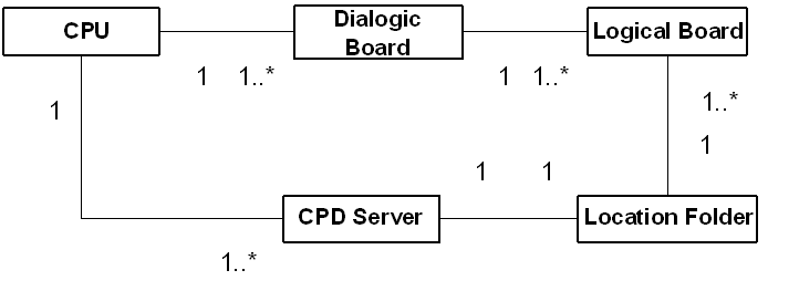
A logical structure describes a single configuration of many boards. Every logical board in a configuration is given a unique logical board number based on the order in which the boards are configured. See Configuring Dialogic Boards.
Genesys recommends a 1-to-1 relationship between the CPU, CPD Server, and the Location folder.
| Note: | The number 1 in the preceding diagram shows a 1-to-1 representation, and 1...* shows a 1-to-more-than-1 representation. |
The following describes what each item in Configuring Dialogic Boards represents:
- Box—Represents a CPU (central processing unit of a computer running on a Windows operating system), where the Dialogic boards and CPD Servers are installed.
- Dialogic Board—Represents a hardware board installed into the CPU. The CPU may have more than one board installed.
- Logical Board—A logical part of the hardware board representing four analog or digital resources (for example, dxxxB1 and all the hierarchy belonging to it). One hardware board consists of several logical boards. One logical board belongs to only one hardware board.
- CPD Server—Represents a piece of software installed on the box. It can be one or more different CPD Server installations.
- Location Folder—Represents a set of logical boards, and one CPD Server. A Location Folder is allowed to have logical boards connected to different hardware boards (see example below). Genesys recommends that you set up a 1-to-1 association between CPD Server applications and the Locations folder.
Considerations
- The Location folder may have logical boards belonging to hardware boards installed in one, and only one, computer running on the Windows operating system.
- If you have two or more different Location folders, they must not have the same logical board configured.
- If you have more than one hardware board installed in the same computer, then the first board (minimal hardware ID) has 1—n logical boards numbering (dxxxB1—dxxxBn), the second board (next ID) has n+1—m (m > n+1) logical boards numbering (dxxxB<n+1>—dxxxBm), and so on. If a logical board is removed from a configuration, then all other logical boards in the configuration must be renumbered to preserve a logical numbering system.
CPD Server Dialogic Hardware Setup in Genesys Administrator
Genesys Administrator simplifies the configuration of the Dialogic hardware in the Configuration Database. When you configure the Dialogic hardware by going to Provisioning > Outbound Contact > Dialogic Boards, Genesys Administrator creates all of the folders and subfolders, based on the selected Dialogic Board and line type. For more information, see Framework Genesys Administrator Help.
You can also manually configure provides the Dialogic hardware, per the guidelines the follow.
Manually Setting Up Your Dialogic Hardware
Start
- In either Genesys Administrator or Configuration Manager, create the Location folder in the Switch DN folder.
- Create three subfolders that will contain board resource subfolders with the names:
- engaging (should contain only DM3 (Melcas) resources of Dialogic board)
- recording (should contain only voice resources)
- regular (can contain any type of Dialogic resources)
Note: These board resource subfolder names should be the same as the virtual board names used for the Dialogic hardware that is installed. - In each of these three subfolders, create another group of board resource subfolders named exactly as the individual channels of the corresponding virtual board.
- In each channel subfolder, include the real DN (Extension) or virtual DN (Call Processing Port) that corresponds to the DN assigned to the board channel.
- For voice-processing ports and ISDN or Melcas virtual channels, you must assign unique numbers to the Call-Processing port DN type.
- For LSI and T1/E1 ports, you should assign the Extension DN type and real channel numbers that are recognizable by the switch.
Note: The ACD Position DN type is not a valid value for CPD Server DNs. - The Register check box should be cleared (unchecked) for CPP and selected (checked) for ACD Extension DNs.
End
Dialogic Board Configuration
The following includes configuration information you can use to configure ASM (ISDN and Melcas), Analog, or T1/E1 line-side protocols.
| Note: | The figures in this topic reflect the configuration as it would appear in Configuration Manager. |
ASM Mode
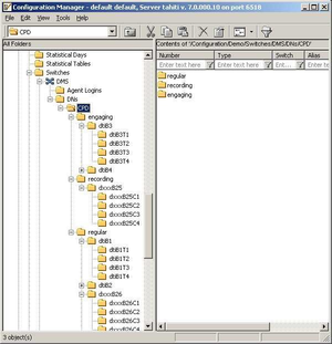
An ASM configuration must have at least one digital board and one voice board in the regular folder. The following figure shows the directory structure for an ISDN or Melcas board.
In the ISDN and Melcas configurations, network resources are associated with DNs of Call Processing Port type. The following figure shows a call processing port DN in an ASM configuration.
Analog
An Analog board configuration must have the following folders and subfolders in this type of directory structure:
- A regular folder
- At least one dxxxB<n> folder within the regular folder
- At least one dxxxB<n>C<n> subfolder within the dxxxB<n> folder.
- At least one dxxxB<n> folder within the regular folder
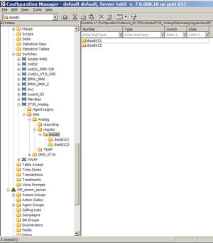
The following figure shows the directory structure for an Analog configuration.
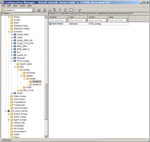
The following figure shows an Extension DN in an Analog configuration.
For more information, see CPD Server Dialogic Hardware Setup in Genesys Administrator.
T1/E1 Line-Side
A T1/E1 line-side configuration must have at least one digital and one voice logical board configured in the regular folder. See the following figure.
In the line-side configuration, each network resource must have one, and only one, DN associated with it. Network resources are associated with DNs of type Extension. See the following figure.
Dialogic Board Configuration Examples
The following figures show sample configurations for ISDN or Melcas (in ASM), Analog, or T1/E1 protocols.
ASM Mode (ISDN or Melcas)
An ASM configuration must have at least one digital board and one voice board in the regular folder.
In the an ASM configuration, network resources are associated with DNs of Call Processing Port type.
The following figure shows a configuration example for an ISDN or Melcas protocol.
Analog Board Configuration
The following figure shows a configuration example for an Analog board.
| Note: | In the 7.x release, the only DN type for an Analog board or a T1/E1 board is Extension, not Position. |
T1/E1 Line-Side Configuration
A line-side configuration must have at least one digital and one voice logical board configured in the regular folder.
In the line-side configuration, network resources are associated with DNs of Extension type.
The following figure shows the configuration example for a T1/E1 Board.
| Note: | Each network resource may have one, and only one, DN associated with it. |
DNs Inside Dialogic Channels Folders
For more information about the Dialogic boards and their channels, see the following documents available on the Genesys Technical Support website:
- Genesys Supported Operating Environment Reference Guide
- Genesys Supported Media Interfaces Reference Manual
New Dialogic Board Configuration
Genesys Administrator simplifies the configuration of the Dialogic hardware in the Configuration Database. When you configure the Dialogic hardware by going to Provisioning > Outbound Contact > Dialogic Boards, Genesys Administrator creates all of the folders and subfolders, based on the selected Dialogic Board and line type. For more information, see Framework Genesys Administrator Help.
You can also configure a new Dialogic board manually, by following the procedure provided here.
Manually Configuring a New Dialogic Board
Start
- In Genesys Administrator, create a <location> folder under the Switch object.
- Under the <location> folder, create a folder named recording.
- Again in the <location> folder, create a folder named engaging.
- Create a folder named regular. For a description of this folder, see CPD Server Dialogic Hardware Setup in Genesys Administrator.
- Configure the regular folder.
Note: A DN can belong to only one channel across the switch.
End


