Configuring BIG-IP LTM
The following page provides an overview of the main steps that are required in order to configure the BIG-IP LTM. Complete all steps in the order in which they are listed.
Integrating with BIG-IP LTM
Verify that BIG-IP LTM is working
The procedures in this topic assume that the BIG-IP LTM is properly licensed and fully functional, with login and password access configured. For more information, see BIG-IP LTM specific documentation.
Configuring VLANs
Purpose
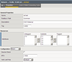
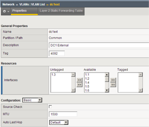
To configure two VLANs (Virtual Local Area Networks): one VLAN for the external interface (physical interface 1.3) and one VLAN for the internal (SIP Server side) interface (physical interface 1.6). VLANs are used to logically associate Self IP interfaces with physical interfaces on the BIG-IP LTM.
Prerequisites
- You are logged in to the BIG-IP LTM web interface.
Start
- Go to Network > VLANs > VLAN List.
- Click Create.
- In the dialog box that appears, specify the following properties:
- Name: Enter the VLAN name for the external interface—for example, dc1ext.
- Tag: 4092 (it is set automatically).
- Resources > Interfaces > Untagged: Select 1.3 in the Available section and click the left-pointing arrow button to move it into the Untagged section.
- Click Finished.
- Click Create.
- In the dialog box that appears, specify the following properties:
- Name: Enter the VLAN name for the internal interface—for example, dc2sip.
- Tag: 4090 (it is set automatically).
- Resources > Interfaces > Untagged: Select 1.6 in the Available section and click the left-pointing arrow button to move it into the Untagged section.
- Click Finished.
End
Configuring Self IP addresses
Purpose
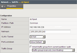
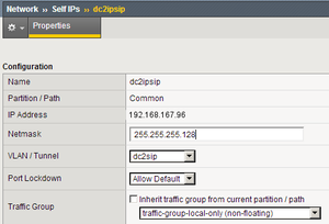
To configure two Self IP addresses—one for the external interface and one for the internal interface—and associate them with the VLANs, to access hosts in those VLANs.
Prerequisites
Start
- Go to Network > Self IPs.
- Click Create.
- In the dialog box that appears, specify the following properties:
- Name: Enter the name for the Self IP address—for example, dc1ipext.
- IP Address: Enter the IP address for the internal interface—for example, 192.168.166.229.
- Netmask: Enter the netmask—for example, 255.255.255.240.
- VLAN: Select the name of the VLAN to which you want to assign the Self IP address—for example, dc1ext.
- Click Finished.
- Click Create.
- In the dialog box that appears, specify the following properties:
- Name: Enter the name for the Self IP address—for example, dc2ipsip.
- IP Address: Enter the IP address for the internal interface—for example, 192.168.167.96.
- Netmask: Enter the netmask—for example, 255.255.255.128.
- VLAN: Select the name of the VLAN to which you want to assign the self IP address—for example, dc2sip.
- Click Finished.
End
Configuring the Default IP route
Purpose
To configure the default IP route.
Prerequisites
Start
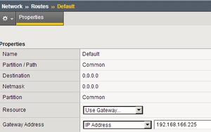
- Go to Network > Routes.
- Click Add.
- In the dialog box that appears, specify the following properties:
- Name: Enter Default.
- Resource: Select Use Gateway.
- Gateway Address: Enter the IP address for this default IP route—for example, 192.168.166.225.
- Click Finished.
End
Configuring SIP Server nodes
Purpose
To configure two SIP Server nodes, primary and backup.
Prerequisites
Start
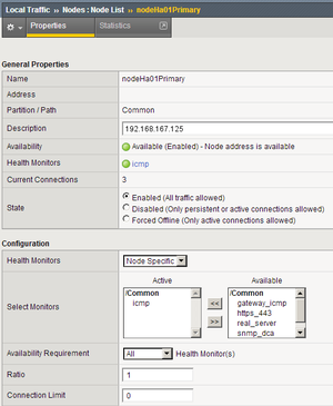
- Go to Local Traffic > Nodes.
- Click Create.
- In the dialog box that appears, specify the following properties:
- Name: Enter the node name—for example, nodeHa01Primary.
- Address: Enter the IP address for the primary SIP Server node—for example, 192.168.167.125.
- Health Monitors: Select Node Specific.
- Select Monitors > Active: Select icmp.
- Click Finished.
- Click Create.
- In the dialog box that appears, specify the following properties:
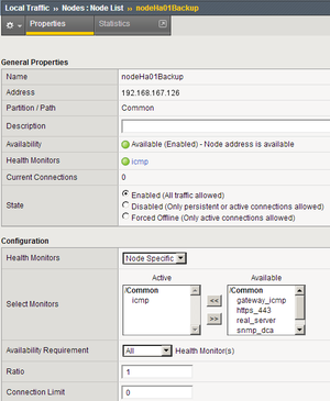
- Name: Enter the node name—for example, nodeHa01Backup.
- Address: Enter the IP address for the backup SIP Server node—for example, 192.168.167.126.
- Health Monitors: Select Node Specific.
- Select Monitors > Active: Select icmp.
- Click Finished.
Configuring a health monitor
In general, the BIG-IP LTM uses health monitors to determine whether a server to which messages can be routed is operational (active). Servers that are flagged as not operational (inactive) will cause the BIG-IP LTM to route messages to another server if one is present in the same server pool. However, primary and backup SIP Servers must be configured as the only members of the same server pool--one member active (primary) and one member inactive (backup).
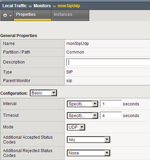
In this procedure, the BIG-IP LTM is configured to use the health monitor of SIP type in UDP mode. This means that the OPTIONS request method will be sent to both primary and backup SIP Servers. Any response to OPTIONS is configured as Accepted Status Code.
SIP Server always starts in backup mode, establishes a permanent connection with the Genesys Management Layer, and changes its role to primary only if a trigger from the Management Layer is received. Such trigger is only generated if no other primary SIP Server is currently running. After switching to primary mode, SIP Server responds to UDP packets received on the SIP port specified by the sip-port configuration option. Therefore, after receiving the OPTIONS request from the BIG-IP LTM, SIP Server responds to the health check, and the BIG-IP LTM marks SIP Server as active.
When running in backup mode, SIP Server ignores UDP messages. Since the BIG-IP LTM does not receive any response to the OPTIONS request, it marks the backup SIP Server as inactive. If SIP Server does not respond because of network latency or other reasons, the BIG-IP LTM will mark SIP Server as inactive, and continue sending ping messages periodically.
The Interval setting defines how often pool members (primary and backup) are checked for presence. The Timeout setting defines the waiting time before an unresponsive member of the pool is marked as inactive. Regardless of the member's status (or SIP Server status), the BIG-IP LTM will always check servers for presence. When an inactive member responds to the health check, it is marked as active. In this configuration, the Interval parameter is set to 1 second and Timeout to 4 seconds in order to minimize a possible delay that might result from a switchover.
Start
- Go to Local Traffic > Monitors.
- Click Create.
- In the dialog box that appears, specify the following properties:
- Name: Enter the name for this health monitor—for example, monSipUdp.
- Type: Select SIP.
- Configuration: Select Basic.
- Interval: Enter 1 (seconds).
- Timeout: Enter 4 (seconds).
- Mode: Select UDP.
- Additional Accepted Status Codes: Select Any.
- Click Finished.
End
Configuring a server pool
Purpose
To configure a server pool with which the BIG-IP LTM will communicate.
Start
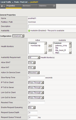
- Go to Local Traffic > Pools.
- Click Create.
- In the dialog box that appears, specify the following properties:
- Name: Enter the name for this server pool—for example, the poolHa01.
- Health Monitors > Active: Select monSipUdp.
- Action On Service Down: Select Reselect.
- Priority Group Activation: Select Disabled.
- Click Finished.
End
Adding server pool members
Purpose
To add primary and backup SIP Servers to the server pool. Note that they must be the only members of this server pool.
Start
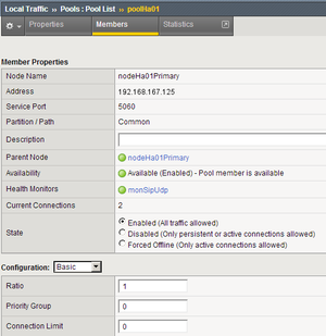
- Go to Local Traffic > Pools > poolHa01 > Members.
- Click Add.
- In the dialog box that appears, specify the following properties:
- Node Name: Select the primary server node you created in Configuring SIP Server nodes. In our example, it would be nodeHa01Primary.
- Address: Specify the IP address of the primary server node. In our example, it would be 192.168.167.125.
- Service Port: Enter 5060.
- Click Finished.
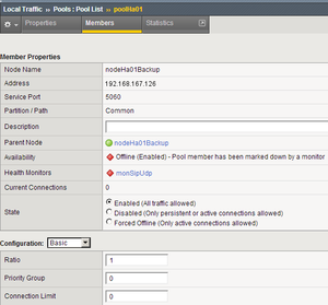
- Click Add.
- In the dialog box that appears, specify the following properties:
- Node Name: Select the backup server node you created in the Configuring SIP Server nodes. In our example, it would be nodeHa01Backup.
- Address: Specify the IP address of the backup server node. In our example, it would be 192.168.167.126.
- Service Port: Enter 5060.
- Click Finished.
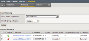
- Set the Load Balancing Method to Round Robin.
- Go to Local Traffic > Pools. The status of the nodeHa01Primary server pool member displays as available (green).
End
Configuring data groups
Purpose
To configure data groups that will be used by the iRule. One data group (dataGroupSnatHa01) contains physical IP addresses of primary and backup SIP Server nodes. The second data group (dataGroupSnatExcludedHa01) contains IP addresses of the systems that will be excluded from applying SNAT, such as Genesys Configuration Server, Genesys Message Servers and other SIP Servers in multi-site deployments (see the Device Communication Groups figure).
Start
- Go to Local Traffic > iRules > Data Group List.
- Click Create.
- In the dialog box that appears, specify the following properties:
- Name: Enter the name for this data group—for example, dataGroupSnatExcludedHa01.
- Type: Select Address.
- Address Records > Type Host > Address: Enter the host IP address of the primary server node—for example, 192.168.167.125.
- Click Add.
- Address Records > Type Host > Address: Enter the host IP address of the backup server node—for example, 192.168.167.126.
- Click Add.
- Click Finished.
- Click Create.
- In the dialog box that appears, specify the following properties:
- Name: Enter the name for this data group—for example, dataGroupSnatExcluded01.
- Type: Select Address.
- Address Records > Type Host > Address: Enter the host IP address of Genesys Configuration Server—for example, 172.21.83.193.
- Click Add.
- Click Finished.
End
Configuring a SNAT pool
Purpose
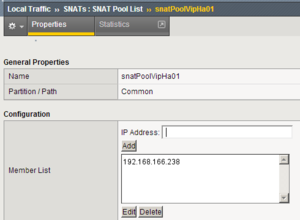
To configure a SNAT pool that specifies the Virtual IP address to be used as a source IP address for any packet that originates from the primary or backup SIP Server to which SNAT is applied (with the exception of the devices specified in the dataGroupSnatExcluded01 data group). SNAT is the mapping of one or more original IP addresses to a translation address.
Start
- Go to Local Traffic > SNATs.
- Click Create.
- In the dialog box that appears, specify the following properties:
- Name: Enter the name for this SNAT pool—for example, snatPoolVipHa01.
- Configuration > Members List > IP Address: Enter the IP address to be used as a source IP address—for example, 192.168.166.238.
- Click Add.
- Click Finished.
End
Configuring an iRule
Purpose
To configure an iRule that is used to perform SNAT to the Virtual IP address to any packets that originate from the primary or backup SIP Server (with the exception of the packets addressed to Configuration Server and the Genesys T-Library Clients group). This iRule will then be associated with a Virtual Server for the outbound traffic, vsWildCardOutbound. In this deployment architecture, the HA synchronization traffic between primary and backup SIP Servers does not pass through the BIG-IP LTM, that is why it is excluded from applying SNAT.
Start
- Go to Local Traffic > iRules.
- Click Create.
- In the dialog box that appears, specify the following properties:
- Name: Enter the name for this iRule—for example, iRuleSnatOutboundHa01.
- Definition: Enter the following text:
#======================================================#
# Apply SNAT as specified in snatPoolVipHa01 for all
# packets originated from dataGroupSnatHa01 members.
# Exclude packets addressed to members of
# dataGroupSnatExcludedHa01.
#======================================================#
when CLIENT_ACCEPTED {
  if { [class match [IP::remote_addr] equals dataGroupSnatHa01] }
  {
    if { [class match [IP::local_addr] equals dataGroupSnatExcludedHa01] }
    {
    }
    else
    {
      snatpool snatPoolVipHa01
    }
  }
}
- Click Finished.
End
Configuring a Virtual Server
Complete the following steps:
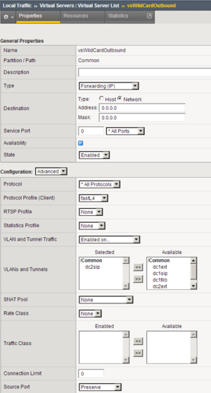
[+] Configuring a Virtual Server for outbound traffic
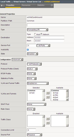
[+] Configuring a Virtual Server for inbound traffic
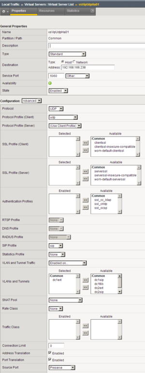
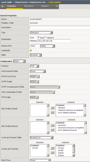
[+] Configuring Virtual Servers for UDP and TCP SIP communications
Note: SNAT pool must not be activated as the configuration element of Virtual Server. SNAT must not be applied to SIP messages sent by clients to SIP Server. Enabling SNAT for these messages results in a broken call flow, as in some circumstances the SNAT is not aligned with SIP Protocol.
<verttabber>

